


 English
 русский
 Español
 عربى
 中文简体

News
Home / News / Industry news / How Far Can a Fiber Optic Cable Be Run? Real Distance Limits Explained

Content
A rural crew I worked with had 3.4 km between the splice closure at the highway junction and a customer's gate, one 4 km drum on the truck, and a switch port fitted with a 10GBASE-LR module. The cable length was never the issue. The optics were. That is the practical shape of this question: single-mode glass will carry a signal for tens of kilometres, but the transceiver at each end, the number of splices in between and the route itself usually decide the answer long before the fiber does.
A single-mode link commonly reaches 10 km on 10GBASE-LR optics, 40 km on ER optics, 80 km on ZR optics, and 100 km or more with coherent line systems plus amplification. A multimode link is usually capped between 300 m and 550 m at 10 Gbps. The cable is essentially the same in all of those cases; only the interfaces change.
Cable datasheets do not quote distance. They quote attenuation, typically 0.35 dB/km at 1310 nm and 0.20 dB/km at 1550 nm for standard G.652D single-mode fiber. Everything after that is arithmetic. Three factors set the final number:
Single-mode fiber has no fixed maximum length. Its working reach is set by the transceiver standard installed at each end, and the standard figures are predictable enough to design around.
| Interface | Typical reach | Wavelength | Practical note |
| 1000BASE-LX | 10 km | 1310 nm | Workhorse 1G long-reach module |
| 10GBASE-LR | 10 km | 1310 nm | Standard for metro and campus links |
| 10GBASE-ER | 40 km | 1550 nm | May need a pad on very short spans |
| 10GBASE-ZR | 80 km | 1550 nm | Vendor specific; check dispersion penalty |
| Coherent 100G or 400G | 80 to 120 km | 1550 nm | DSP compensates dispersion; amplification extends span |
Past 80 km, distance stops being a cable question and becomes a system design exercise. Coherent ports handle chromatic dispersion digitally and reach 80 to 120 km without regeneration, inline amplification pushes spans beyond 100 km, and unrepeatered spans of 200 km or more are achievable on well-engineered routes. Submarine systems with repeaters run into thousands of kilometres. The glass never changes: it is the same 9-micron core, lit differently.
Multimode distance is limited by modal dispersion rather than attenuation, and the Ethernet standards translate that into fixed numbers you can plan against.
At 40G and 100G the figures tighten further: OM3 is typically limited to about 100 m and OM4 to about 150 m on parallel optics, while 1000BASE-LX over multimode uses mode-conditioning cords to reach 550 m. Multimode is in-building and data centre material. Once a route leaves the building, single-mode usually wins on total cost, because the electronics are simpler to upgrade later.
A loss budget is the difference between the launch power of the transmitter and the sensitivity of the receiver. The link works only if fiber loss, splices, connectors and ageing margin stay under that figure at the worst case.
Run the arithmetic on a real example. A 12 km span on 1310 nm optics carries 4.2 dB of fiber, 0.8 dB of connectors, 0.3 dB for three splices and 3 dB of margin, for 8.3 dB total. A 10GBASE-LR port has roughly 6.2 dB, so that link does not close. ER optics at 1550 nm, where attenuation falls to about 0.22 dB/km, do close it with a comfortable margin.
Installation distance and transmission distance are two different numbers, and confusing them is what turns a clean design into a mid-project reorder. A cable can only be pulled as far as its tension rating, bend radius and drum length allow.
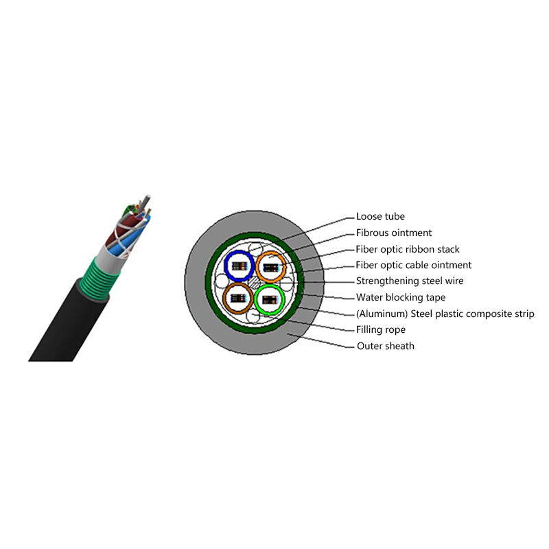
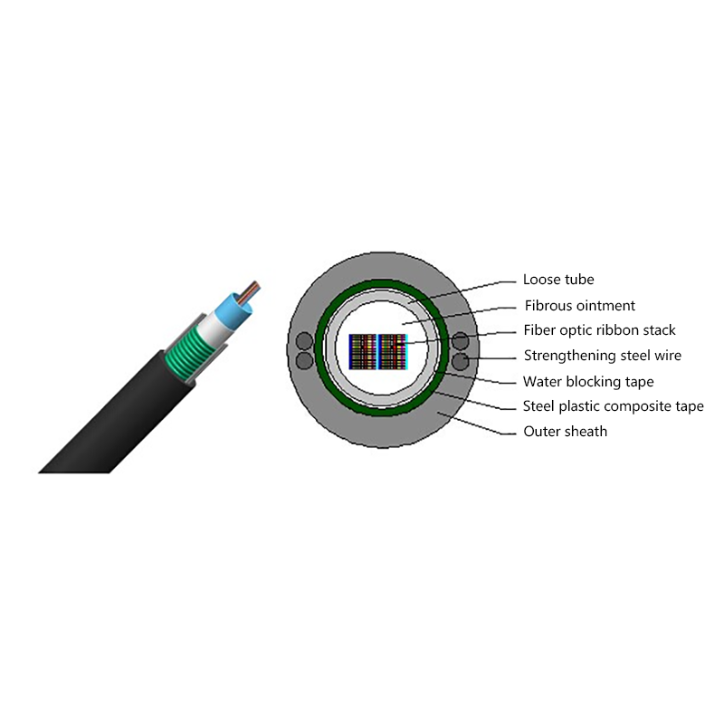
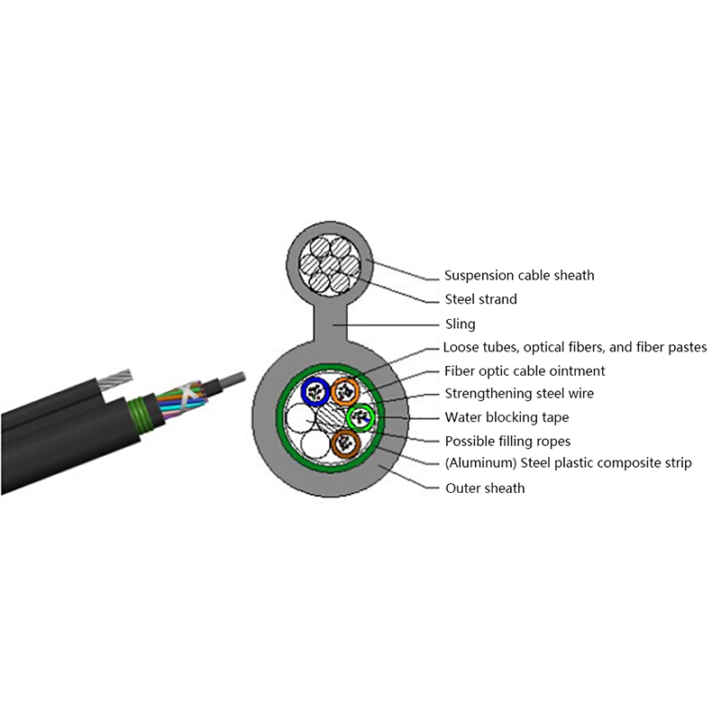
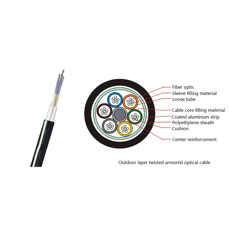
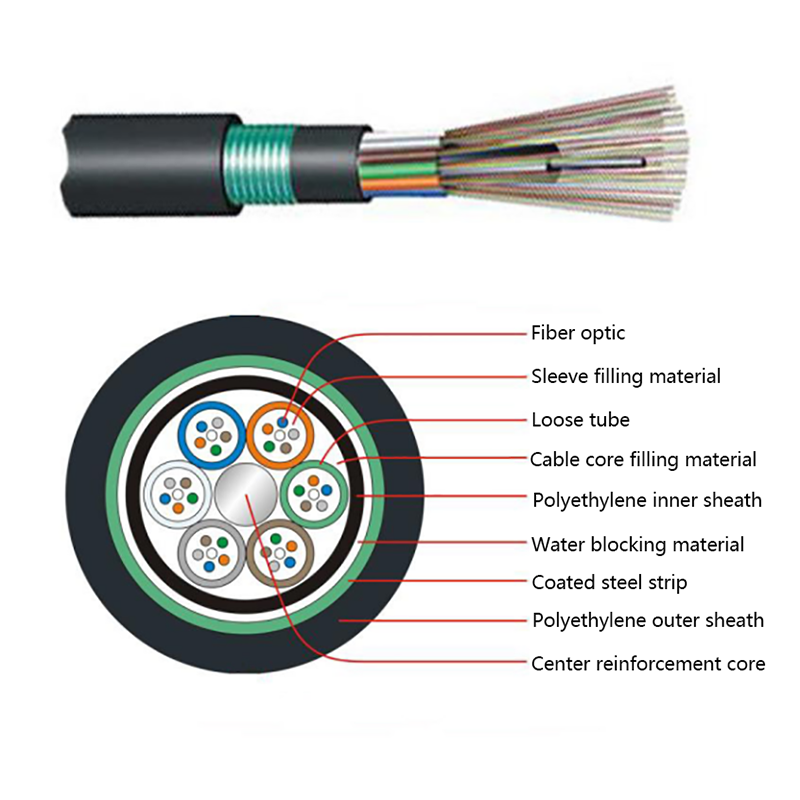
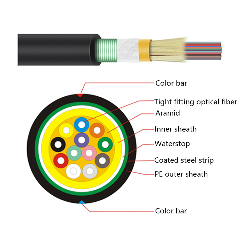
Duct cable ships in 2 km or 4 km lengths, with short-term tension ratings typically around 1500 N to 2700 N and a bend radius of 20 times the cable diameter during the pull, easing to 10 to 15 times once installed. Long pulls need lubricated duct, intermediate chambers or figure-eighting. Where a route mixes buried duct with pole line, the construction matters as much as the distance, because an armored duct design and a self-supporting aerial design are not interchangeable.
If the route crosses that boundary, read this underground and aerial installation guide before specifying the sheath.
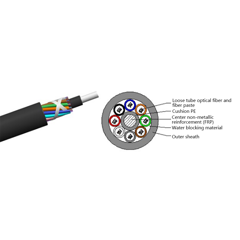
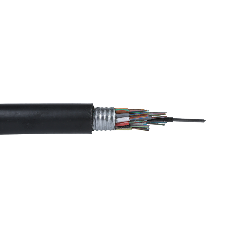 GYTS Outdoor Steel-Polyethylene Bonded Sheath Fiber CableReview this outdoor loose-tube cable for its bonded steel-polyethylene sheath and water-blocking grease when choosing sheathing for route transitions.View Product →
On pole lines and microduct networks, distance is set by span engineering and duct length rather than by attenuation. ADSS spans commonly run 100 m to 500 m between structures, while air-blown microcable is installed 1 km to 2 km per push into ducts that may run for many kilometres in total.
ADSS design is driven by sag, wind and ice loading plus the permitted tension at the pole, so the fiber itself is rarely the constraint: the same 24-fiber unit can serve a 120 m road crossing or a 400 m river span depending on sheath and hardware. Microcable works the other way round. The duct is placed once over the full route and the fiber is blown in later, so the practical limit is the number of push points and the duct bore, not the optical reach of the cable.
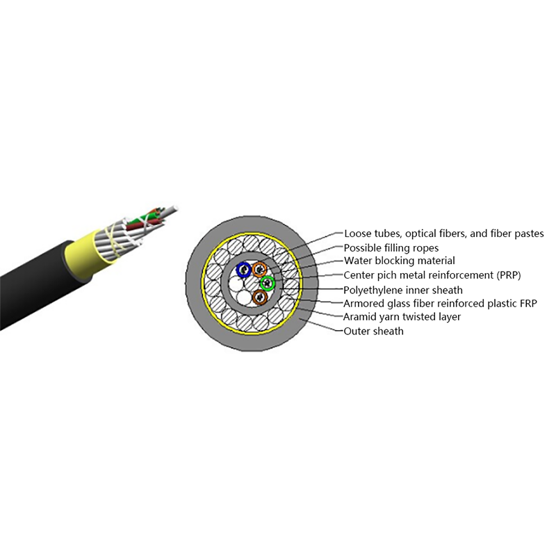
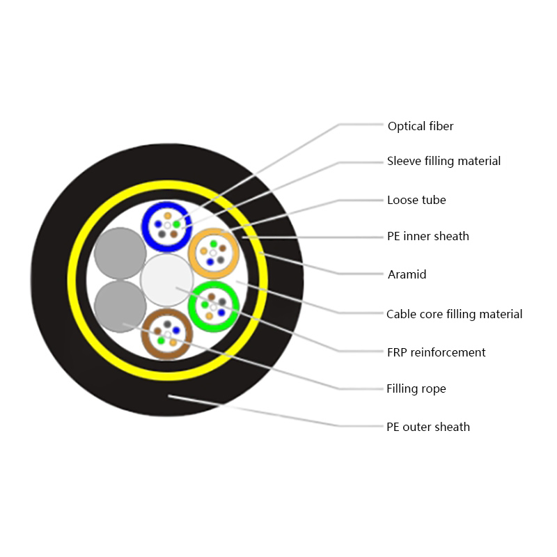 ADSS All-Dielectric Self-Supporting Aerial Fiber CableReview this fully dielectric aerial cable with aramid yarn reinforcement and FRP strength member; aramid cross-section can be adjusted for different span and sag requirements.View Product →
Work through these in order and the distance question answers itself before anything is ordered.
Single-mode reaches 10 km on LR optics, 40 km on ER and 80 km on ZR with no amplification at all. Coherent systems reach 80 to 120 km unregenerated, and amplified line systems extend that past 100 km per span.
Yes, comfortably. 1,000 feet is about 305 m, which sits well inside the range of multimode at 10G and inside any single-mode interface. At that distance the splice and connector count matters far more than the glass.
Only marginally. Light travels through fiber at roughly 5 microseconds per kilometre, so a 20 km link adds about 0.1 ms of latency, which is below the jitter most routers and switches introduce anyway.
Usually 2 km to 4 km per drum for duct cable, and less for high fiber counts or routes with many bends. Tension, bend radius and pull geometry set that limit, which is why long routes are built from several drum lengths joined at splice closures.

Request for a call today

 Login
Custom Optical Cables Manufacturers