


 English
 русский
 Español
 عربى
عربى 中文简体
中文简体

Optoelectronic Composite Cable: Unified Power & Data Transmission
Content
Optoelectronic composite cables deliver a unified transmission medium that carries both electrical power and high-speed optical data within a single protective sheath. By eliminating the need for separate cable runs, they reduce installation complexity and material costs by up to 30 percent while maintaining signal integrity over distances exceeding 10 kilometers. This hybrid design provides an immediate answer to the growing demand for compact, interference-resistant connectivity in dense urban and industrial environments.
Core Structure and Transmission Principles
The cable integrates two distinct pathways inside a single jacket. Optical fibers, typically single-mode or multimode, handle data transmission using light signals that are inherently immune to electromagnetic interference. Alongside them, stranded copper conductors carry low-voltage power, often up to 1 kV, with cross-sections chosen for the required current. A common configuration places the optical units in a central loose tube surrounded by insulated copper wires, all wrapped in strength members, water-blocking tape, and an outer polyethylene or low-smoke zero-halogen sheath. Metallic armoring can be added for direct burial applications.
This combined construction means that a single cable replaces two separate infrastructure elements, occupying less conduit fill and simplifying cable tray layouts. The physical separation between the optical and electrical components, reinforced by non-conductive strength elements, prevents any performance cross-talk. Fiber attenuation remains as low as 0.35 dB per kilometer at 1310 nm, identical to standalone fiber cables, while copper voltage drop is managed through appropriate conductor sizing.
Measurable Benefits in Network Deployment
Comparing a typical installation using separate power and fiber cables against an optoelectronic composite cable reveals clear operational advantages. The table below summarizes data gathered from urban infrastructure projects.
| Parameter | Separate Cables | Optoelectronic Composite Cable |
|---|---|---|
| Average installation time per 100 m | 14 labor hours | 9 labor hours |
| Total cable weight per 100 m | 42 kg | 28 kg |
| Conduit space occupancy | 68 percent | 41 percent |
| Material cost index | 100 | 72 |
The composite solution consistently reduces labor hours, weight, and conduit occupancy. The material cost index, with separate cables set at 100, shows that the composite option lowers upfront material expenditure by around 28 percent. These savings compound across large-scale deployments such as campus networks and metropolitan small-cell rollouts.
Critical Applications Driving Adoption
Several sectors now depend on the hybrid nature of optoelectronic composite cables to simplify infrastructure while improving performance.
- Intelligent transportation systems: Roadside units for traffic monitoring, license plate recognition, and dynamic signage receive both power and gigabit data through a single cable, reducing pole clutter and maintenance access windows.
- Industrial automation: Factory floors connect sensors, cameras, and actuators across long production lines. The optical path ensures deterministic data delivery free from motor-drive noise, while copper powers field devices.
- 5G and small-cell fronthaul: Remote radio units on street furniture require both DC power and high-throughput backhaul. A single composite cable streamlines permitting and installation on shared utility poles.
- Smart city and IoT networks: Environmental sensors, public Wi-Fi access points, and surveillance cameras in parks or along roads benefit from unified power and data delivery, cutting the number of service pedestals by half.
- Renewable energy monitoring: Solar farms and wind turbine arrays use composite cables to connect photovoltaic trackers or nacelle sensors back to control rooms, combining auxiliary power and real-time telemetry over kilometers of terrain.
In each case, deploying a single optoelectronic composite cable instead of two independent ones can shorten project completion by several days and reduce the number of required connection points, which in turn lowers ongoing maintenance effort.
Installation and Maintenance Best Practices
Proper handling ensures that the hybrid cable meets its full performance and lifespan potential. Field experience highlights several practices that consistently deliver reliable results.
- Maintain minimum bend radius. The dynamic bend radius should stay above 20 times the outer cable diameter during pulling, and the static radius above 10 times after installation, preventing stress on both fibers and conductors.
- Use hybrid connectors. Pre-terminated hybrid connectors that simultaneously align optical ferrules and electrical pins reduce field termination errors and guarantee consistent contact resistance below 5 milliohms.
- Perform sequential testing. Verify optical continuity and insertion loss with an OTDR before energizing the power conductors. Then confirm insulation resistance exceeds 100 megohms at 500 V DC before commissioning.
- Segregate grounding. The cable’s metallic armor and any copper drain wire must be grounded according to local electrical codes, but the optical path requires isolated handling to avoid ground loop currents.
- Label clearly. Because the cable carries both low-voltage power and data, all termination boxes and patch panels need unambiguous labeling to prevent accidental misconnection during future moves or upgrades.
Performance Under Electromagnetic Interference
A key reason for adopting optoelectronic composite cables in heavy electrical environments is the complete immunity of the optical channel to electromagnetic noise. Even when the copper conductors carry fluctuating currents that generate magnetic fields, the glass fibers remain unaffected. Measurements in a 400 V, 50 Hz industrial setting showed zero increase in bit error rate on the fiber link compared to a control cable without power conductors. This property makes the cable especially valuable in railway signaling, high-voltage substation monitoring, and factory automation, where inductive interference routinely disrupts Ethernet over copper alone.
Moreover, the physical design keeps the fiber away from direct contact with current-carrying elements. Dielectric strength members and buffer tubes ensure that any temperature rise in the copper does not push the fiber beyond its operating range of -40 degrees Celsius to +70 degrees Celsius, preserving long-term optical stability.
Long-Term Reliability and Durability
Service life expectations for optoelectronic composite cables typically extend beyond 25 years when installed within specified environmental limits. Outer jackets made from UV-stabilized polyethylene or low-smoke zero-halogen compounds resist cracking and chemical exposure. Water-blocking yarns and swellable tapes prevent moisture ingress in underground ducts, while corrugated steel tape armor provides crush resistance exceeding 4000 N per 100 mm. Routine inspection programs that combine optical time-domain reflectometry with insulation resistance checks can catch early degradation signs and prevent unplanned downtime.
Because the integrated approach eliminates a separate power cable, fewer components are exposed to environmental wear, which translates to a lower total cost of ownership over decades. This durability is driving adoption in offshore wind connections, remote mining communications, and other harsh-environment deployments where maintenance access is difficult and costly.
Related Products
-
Optical Phase Conductor OPPC Cable
-
GYXTW Central Tube Armored Outdoor Optical Cable
-
Fiber Optic Patch Cables
-
OPGW Optical Fiber Composite Overhead Ground Wire
-
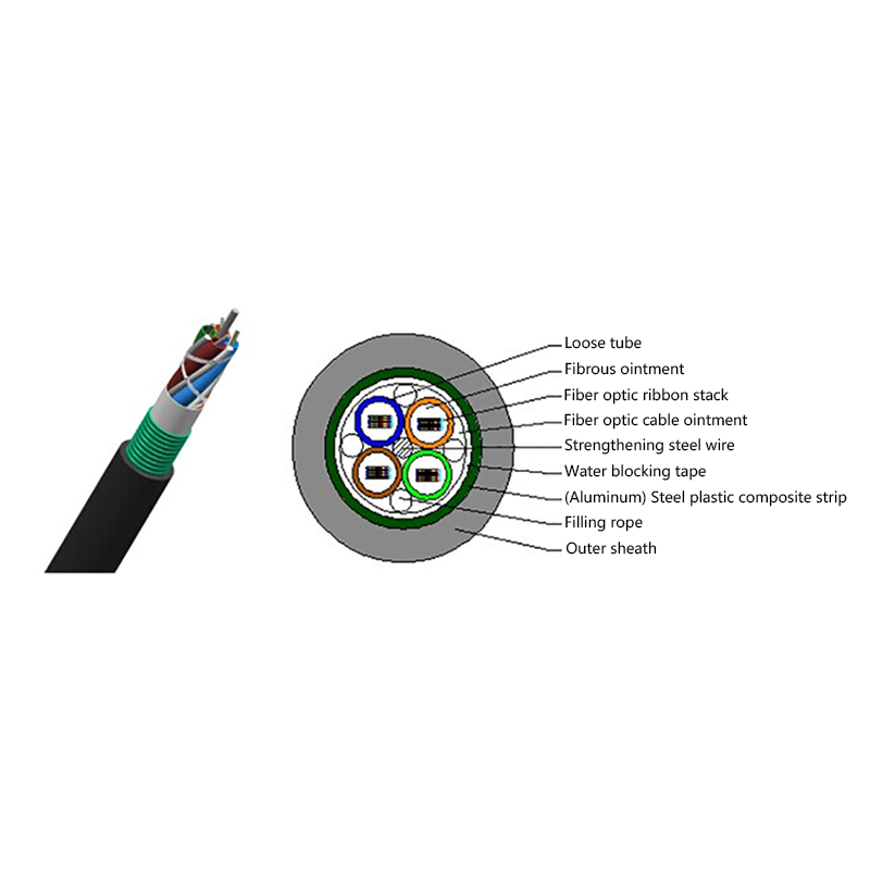
GYDTA(S) Layer Stranded Optical Fiber Ribbon Cable
-
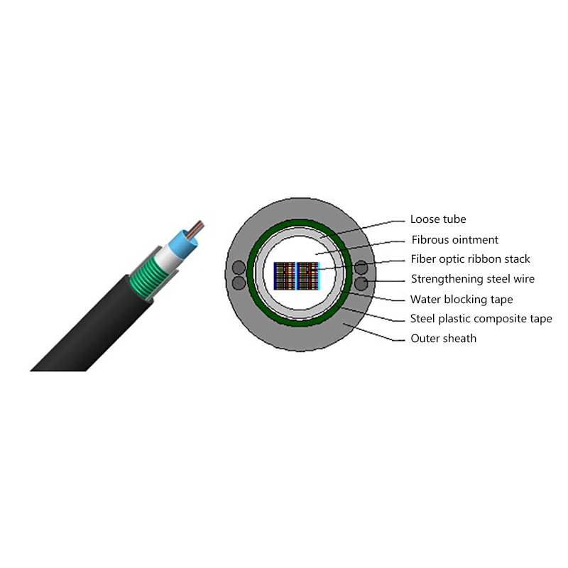
GYDXTW Center Tube Outdoor Optical Fiber Ribbon Cable
-
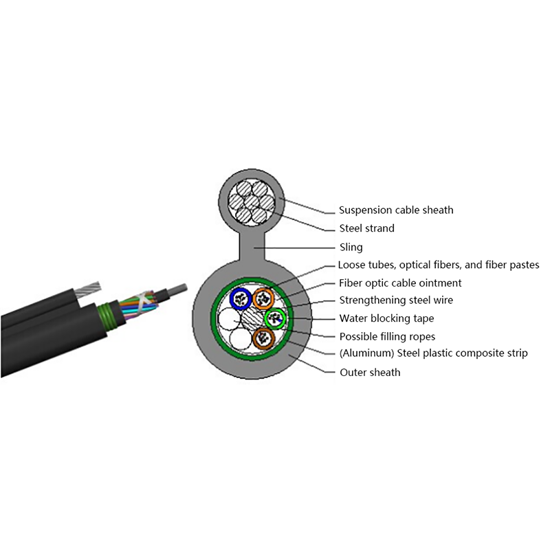
GYTC8A (S) Outdoor layer Stranded 8-shaped Self-Supporting Optical Cable
-
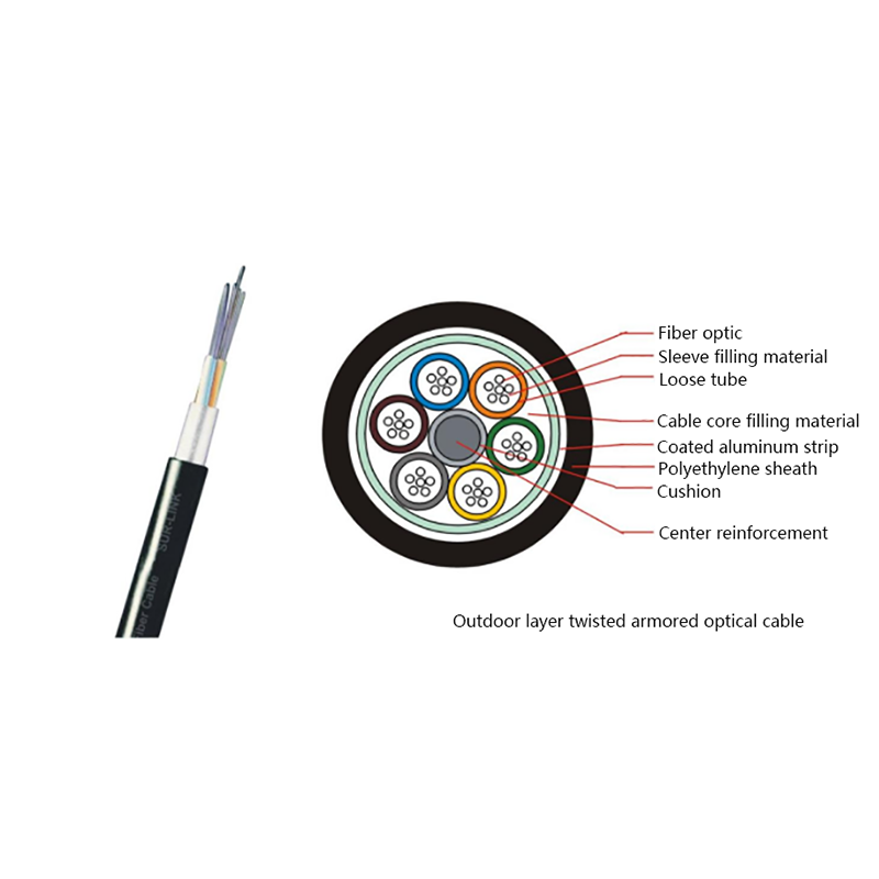
GYTA Layer Stranded Aluminum-Polyethylene Bonded Sheathed Outdoor Optical Cable
-
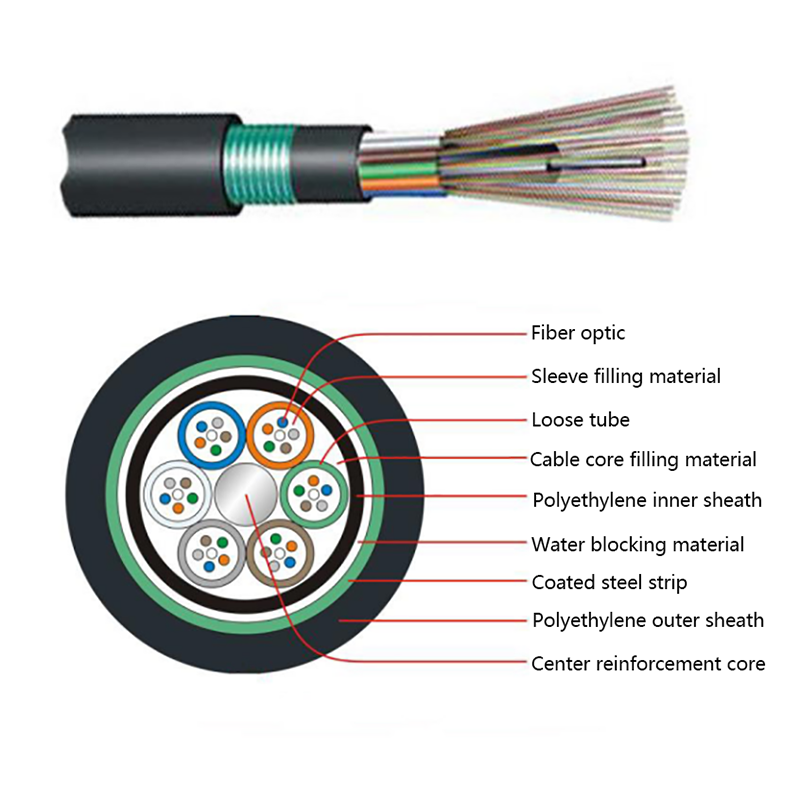
GYTY53 Layer-Stranded PE Inner Sheathed Steel Tape Armored Outer Sheath Optical Cable
-
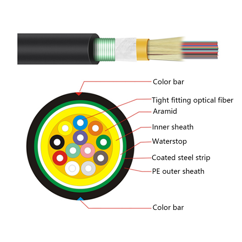
GJFJH53 Indoor Bundled Steel Tape Armored Optical Cable
-

GJPFJV GJFJHV Indoor Branch Optical Cable
-
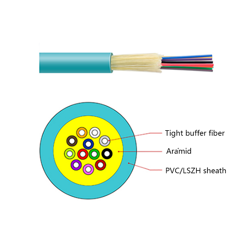
GJFJV Indoor Single Bundle Fiber Optical Cable
-
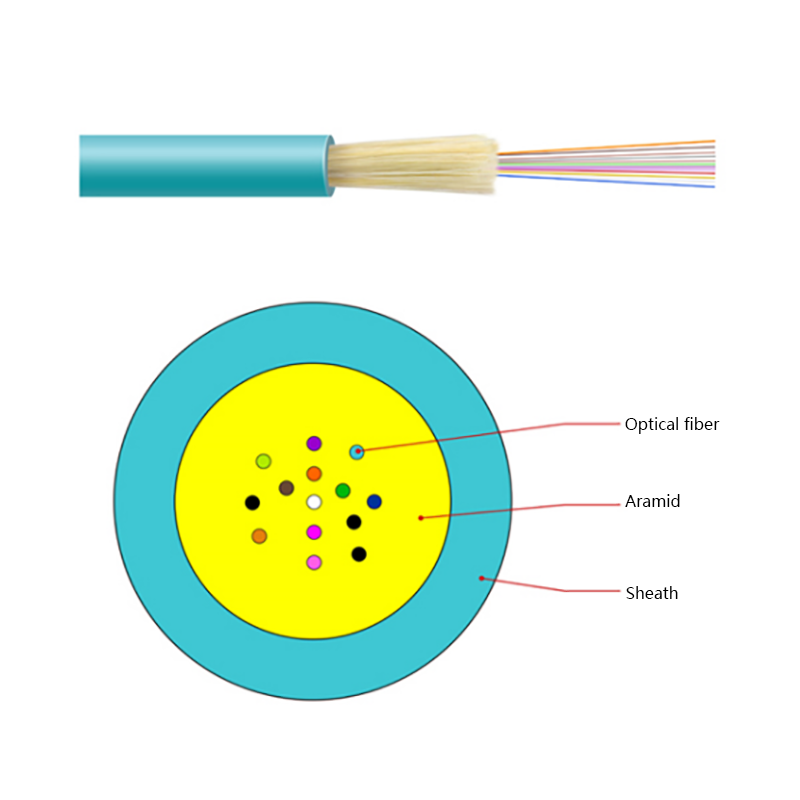
GJFV Indoor Mini Bundle Fiber Optic Cable
-
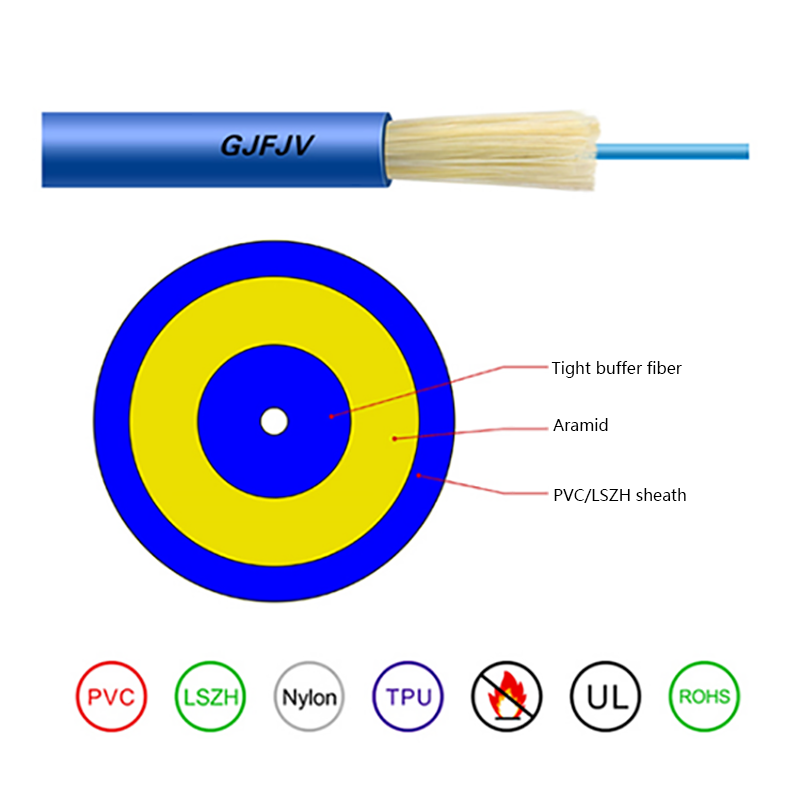
GJFJV Indoor Single Core Jumper Wire Optical Cable
-
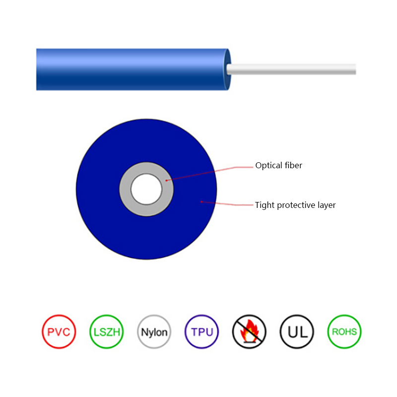
Indoor Tight-Buffered Fibre Optic Cable
-
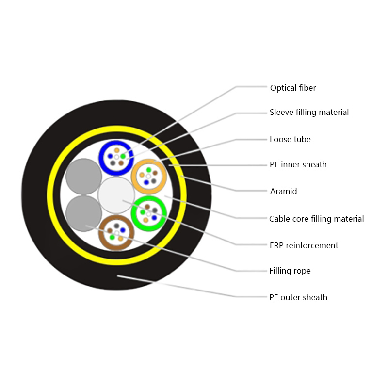
ADSS—All-Dielectric Self-Supporting Optical Cable
-
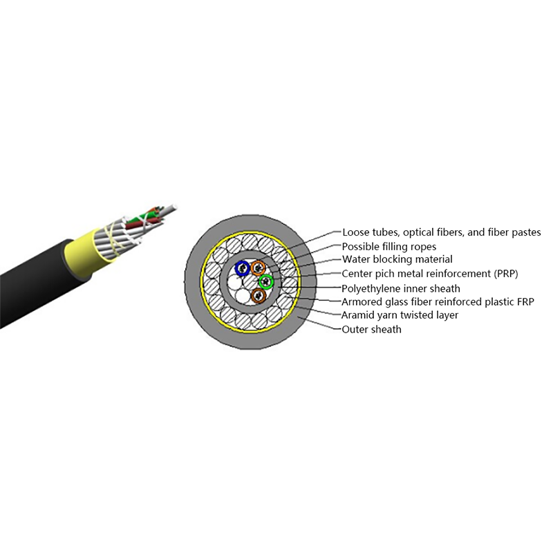
Anti-Squirrel ADSS Optical Cable
-
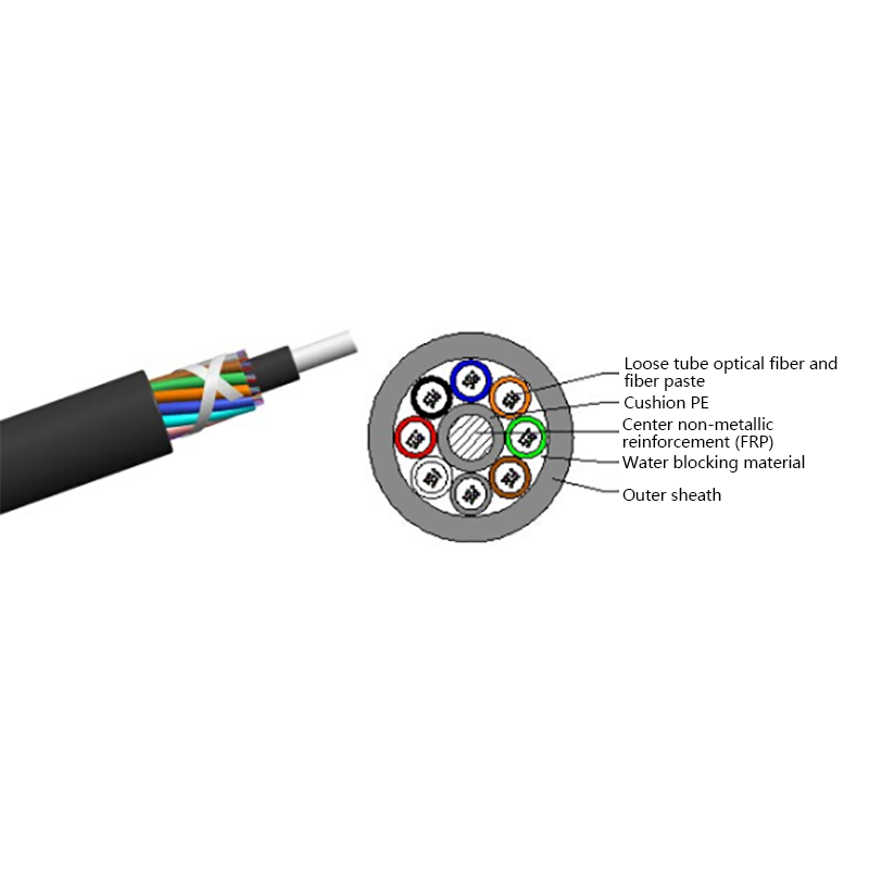
Non-metallic optical cable
Looking For Bussiness Opportunity?
Request for a call today

- Tel: +86-139-6297-6666
- Whatsapp: +86-13962991888
- E-mail: [email protected] / [email protected]
- Add: No.18, Xinjing Road, Nantong Economic and Technological Development Zone, Jiangsu Province, China
Products
Message
Coprright 2023 Jiangsu Hawell Optoelectronic Technology Co., Ltd. All Rights Reserved
 Login
Custom Optical Cables Manufacturers
Login
Custom Optical Cables Manufacturers
Login
Custom Optical Cables Manufacturers