


 English
 русский
 Español
 عربى
عربى 中文简体
中文简体

ADSS Cable: Prevent Costly Downtime with All-Dielectric Fiber
Content
- 1 What an ADSS Cable Failure Actually Costs
- 2 What Is ADSS Cable?
- 3 Construction and Key Components
- 4 When to Choose ADSS Over Other Fiber Cables
- 5 Installation Considerations That Determine Longevity
- 6 Typical ADSS Cable Specifications
- 7 Selection Criteria: Matching Cable to Application
- 8 Long‑Term Reliability and Maintenance
What an ADSS Cable Failure Actually Costs
A single hour of unplanned downtime on a 69 kV transmission line can exceed $200,000 in lost revenue and emergency repair costs. Yet many network planners still underestimate how the choice of fiber optic cable directly impacts long-term reliability. ADSS cable—All-Dielectric Self-Supporting fiber optic cable—was engineered precisely to remove the main failure points that plague traditional lashed or messenger‑wire installations. It contains no metal, requires no separate support strand, and can be installed directly on high‑voltage structures while the line remains energized. The result is a cable system that eliminates grounding problems, galvanic corrosion, and a large portion of the mechanical hardware inventory—all while meeting the same tensile and sag requirements as conventional alternatives.
What Is ADSS Cable?
ADSS cable is a fiber optic cable designed to be self‑supporting over spans of up to several thousand feet without a metallic messenger wire. Its entire construction—strength members, jacket, and core—uses non‑conductive, dielectric materials. This makes the cable immune to electromagnetic induction from nearby power lines, so it can be attached directly to transmission towers and distribution poles at points where the electric field is manageable. The cable’s self‑supporting nature comes from high‑modulus aramid yarns or fiberglass‑reinforced plastic rods that provide the necessary tensile strength while keeping the cable lightweight.
Construction and Key Components
Optical Core
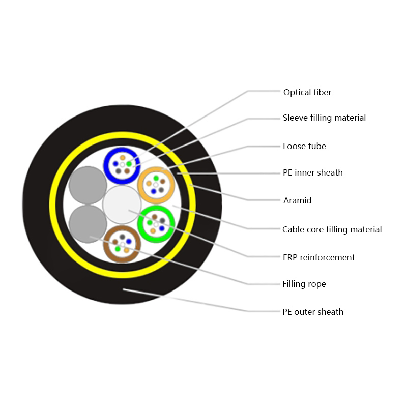
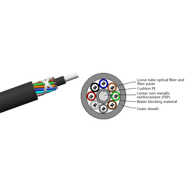
The core contains the actual glass fibers, typically arranged in loose‑tube or tight‑buffered configurations. Loose‑tube designs are preferred for outdoor environments because they isolate fibers from tensile forces and provide room for thermal expansion. Most ADSS cables use up to 288 fibers, with common counts being 12, 24, 48, and 144.
Strength Members
Aramid yarns (e.g., Kevlar) or fiberglass elements provide all tensile and crush resistance. The amount of aramid is calculated for each span length and installation tension, directly controlling sag performance. Cables with insufficient aramid content will exceed maximum sag limits under ice and wind loads, risking clearance violations.
Inner and Outer Jackets
Polyethylene jackets protect the core. Medium‑density polyethylene (MDPE) or high‑density polyethylene (HDPE) is standard. For polluted or coastal environments, a track‑resistant compound is essential to prevent dry‑band arcing and jacket punctures. Jacket thickness and UV stabilizers directly determine the service life—typically 25 to 30 years.
When to Choose ADSS Over Other Fiber Cables
ADSS is not a universal solution, but it is the superior choice in three specific scenarios: installation on live electric utility infrastructure, very long spans where messenger wires become impractical, and environments where metal components would create corrosion or ground‑fault risks. If the route is entirely underground or inside buildings, an armored loose‑tube or indoor/outdoor tight‑buffered cable is more appropriate. On transmission towers, however, ADSS avoids the weight and wind loading of OPGW (Optical Ground Wire) and the complex bonding requirements of lashed dielectric cables.
For any span over 500 ft between structures, the weight savings of ADSS typically reduce total installed cost by 15–25 % compared to a messenger‑supported system.
Installation Considerations That Determine Longevity
Span Length and Sag
Every ADSS installation begins with a sag‑tension calculation based on the ruling span concept. Engineers must input the exact span lengths, elevation differences, and local temperature extremes. The cable is then strung to a specific tension at a reference temperature so it maintains safe clearances at both maximum ice/wind and maximum temperature. Under‑tensioning causes excessive sag and possible conductor contact; over‑tensioning leads to premature fiber strain.
Space Potential and Tracking
When a dielectric cable is suspended in a high electric field, capacitive coupling can cause a surface potential difference. If the field exceeds the jacket’s tracking resistance, dry‑band arcing can erode the jacket within months. Therefore, cable position on the tower must be selected based on electric field modeling. Always specify a track‑resistant jacket if the cable will be installed within 15 ft of an energized conductor at 115 kV or above.
Hardware and Attachment
ADSS cables use specially designed dead‑ends, suspension clamps, and spiral vibration dampers. The hardware must compress the cable without exceeding the manufacturer’s crush rating and must maintain adequate grip under the full rated tensile load. Sharp bending at hardware exit points is a common failure cause—installers must use the correct armor rods or anti‑bend devices.
Typical ADSS Cable Specifications
| Parameter | Typical Value Range | Notes |
|---|---|---|
| Fiber count | 12 to 288 | Split across multiple loose tubes |
| Maximum span length | 200 ft to 4,000 ft | Depends on aramid content and NESC loading district |
| Operating temperature | ‑40 °F to +150 °F | Higher temp requires larger sag allowance |
| Jacket material | MDPE, HDPE, or track‑resistant polyethylene | TR jacket mandatory above 115 kV near conductors |
| Maximum tensile load | 600 lbf to 6,000 lbf | Rated for the NESC heavy loading district if applicable |
Selection Criteria: Matching Cable to Application
Fiber Type and Count
Single‑mode fibers (G.652.D or G.657.A) dominate utility networks. Multi‑mode fibers are rarely used beyond substation LANs. Always specify at least 20 % more fibers than current network needs—adding fibers later is impossible on an existing ADSS span. For long‑haul transmission corridors, 48–144 fibers are standard; distribution feeders often need only 12–24.
Voltage and Electric Field Class
ADSS cables are classified by the maximum space potential they can withstand without tracking. A cable installed in a 230 kV environment 6 ft from the conductor faces a far more aggressive field than the same cable 30 ft away on a dead‑end structure. Always cross‑reference the cable manufacturer’s E‑field tolerance chart with the utility’s modeling data.
Environmental Loadings
The National Electrical Safety Code defines light, medium, and heavy loading districts in the U.S. A cable rated for light loading (no ice, low wind) will fail early in a heavy‑loading region with 0.5 in of radial ice. Confirm that the cable’s design maximum tension, sag, and hardware ratings match the exact geographic loading requirement.
Long‑Term Reliability and Maintenance
When properly designed and installed, ADSS cable requires virtually no maintenance for 25 years. The primary risk factors are unexpected jacket damage from third‑party contact (e.g., gunshots, construction equipment) and progressive tracking in under‑modeled electric field zones. Annual visual inspections from ground level or via drone can identify sag changes or jacket discoloration before a failure occurs. Fiber testing with an OTDR should be repeated after any major storm event to verify splice integrity.
Related Products
-
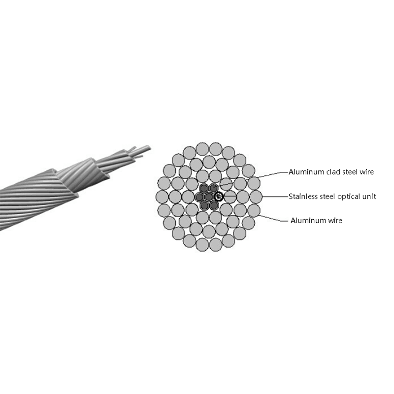
Optical Phase Conductor OPPC Cable
-
GYXTW Central Tube Armored Outdoor Optical Cable
-
Fiber Optic Patch Cables
-
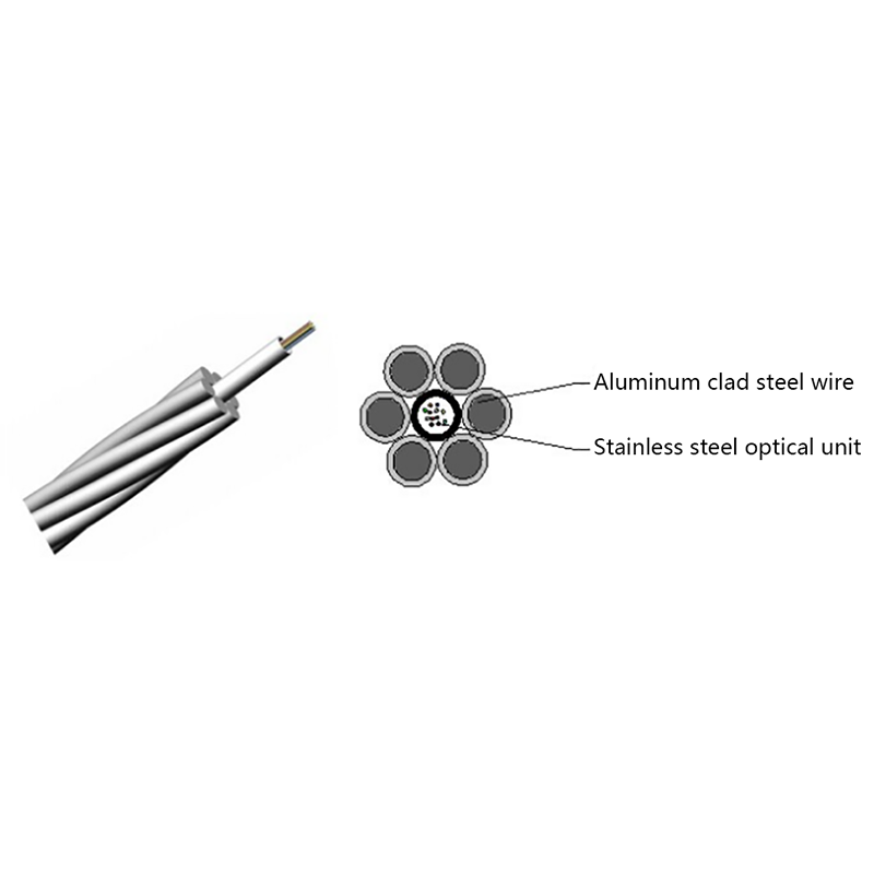
OPGW Optical Fiber Composite Overhead Ground Wire
-
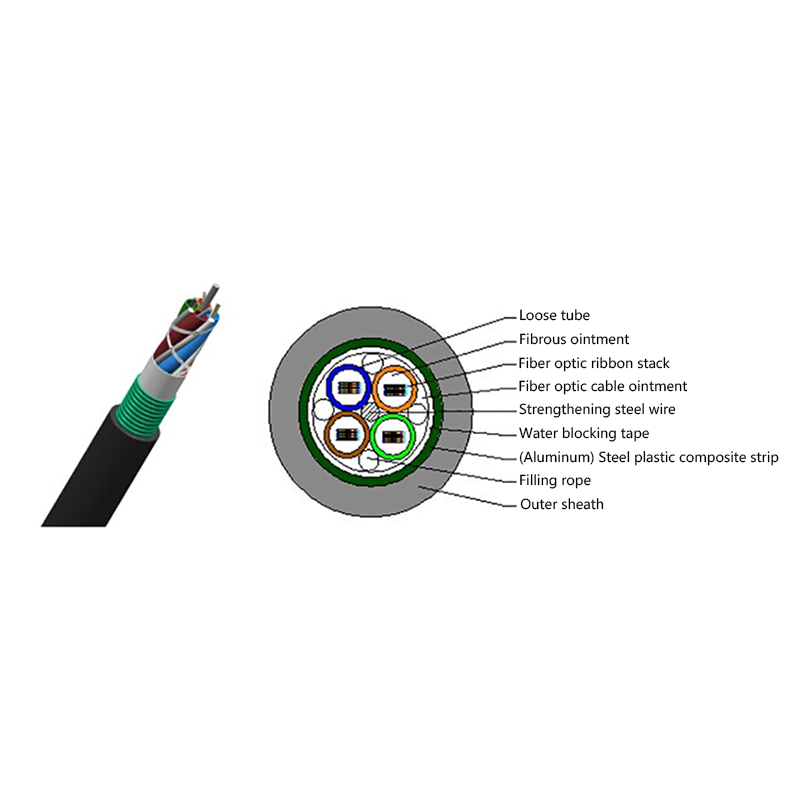
GYDTA(S) Layer Stranded Optical Fiber Ribbon Cable
-
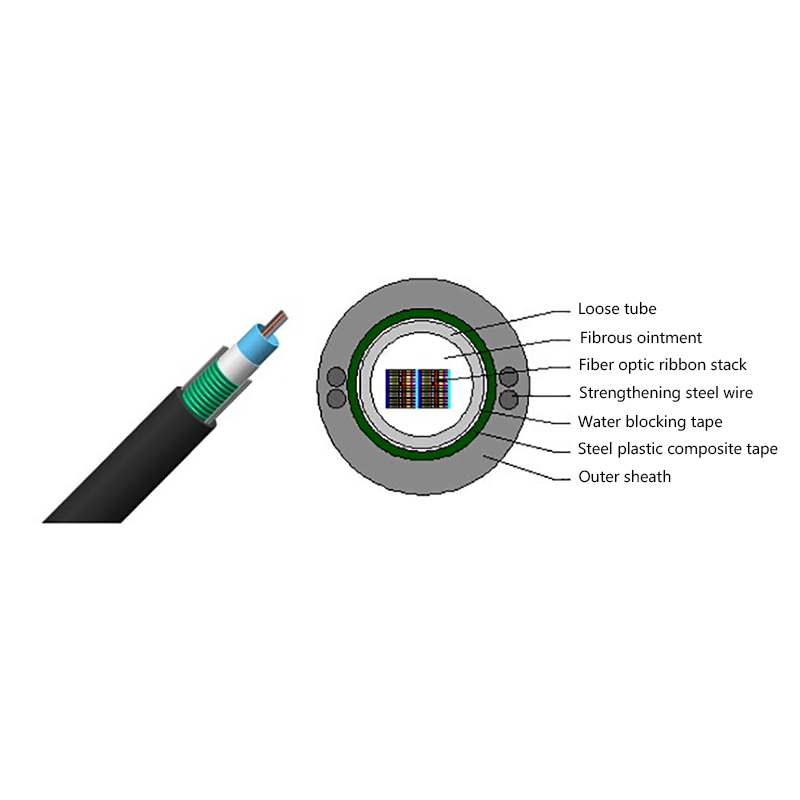
GYDXTW Center Tube Outdoor Optical Fiber Ribbon Cable
-
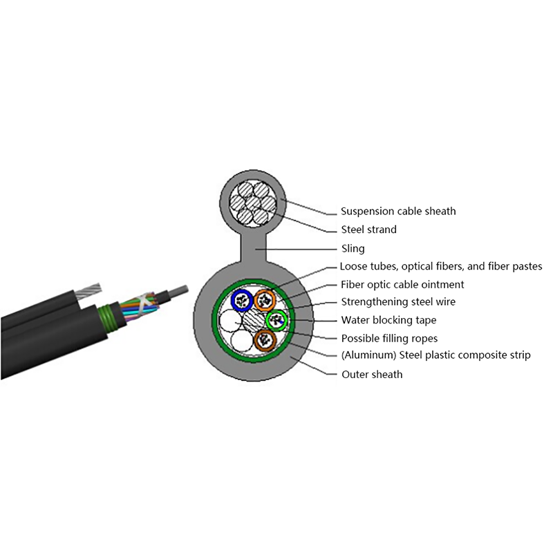
GYTC8A (S) Outdoor layer Stranded 8-shaped Self-Supporting Optical Cable
-
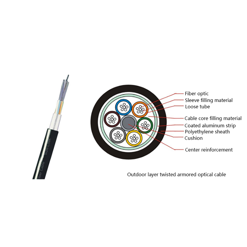
GYTA Layer Stranded Aluminum-Polyethylene Bonded Sheathed Outdoor Optical Cable
-
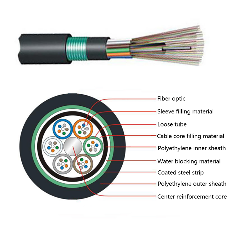
GYTY53 Layer-Stranded PE Inner Sheathed Steel Tape Armored Outer Sheath Optical Cable
-
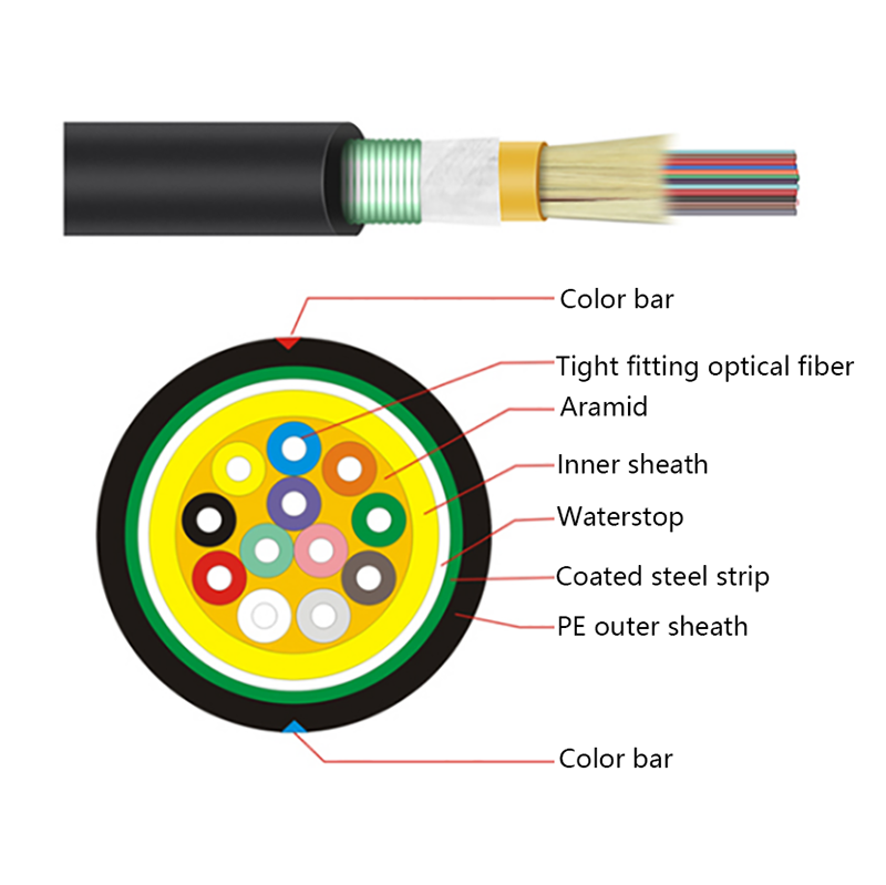
GJFJH53 Indoor Bundled Steel Tape Armored Optical Cable
-

GJPFJV GJFJHV Indoor Branch Optical Cable
-
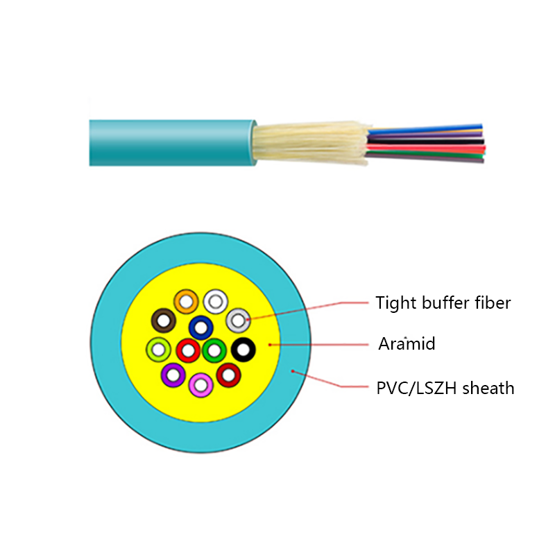
GJFJV Indoor Single Bundle Fiber Optical Cable
-
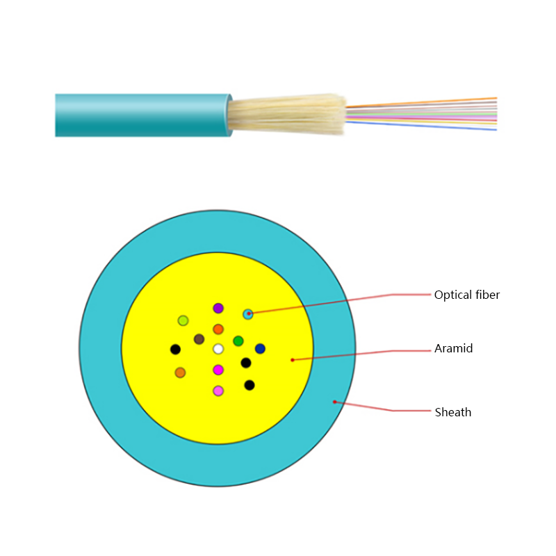
GJFV Indoor Mini Bundle Fiber Optic Cable
-
GJFJV Indoor Single Core Jumper Wire Optical Cable
-
Indoor Tight-Buffered Fibre Optic Cable
-
ADSS—All-Dielectric Self-Supporting Optical Cable
-
Anti-Squirrel ADSS Optical Cable
-
Non-metallic optical cable
Looking For Bussiness Opportunity?
Request for a call today

- Tel: +86-139-6297-6666
- Whatsapp: +86-13962991888
- E-mail: [email protected] / [email protected]
- Add: No.18, Xinjing Road, Nantong Economic and Technological Development Zone, Jiangsu Province, China
Products
Message
Coprright 2023 Jiangsu Hawell Optoelectronic Technology Co., Ltd. All Rights Reserved
 Login
Custom Optical Cables Manufacturers
Login
Custom Optical Cables Manufacturers
Login
Custom Optical Cables Manufacturers