

 English
 русский
 Español
 عربى
عربى 中文简体
中文简体News
Home / News / Industry news / How Are Air Blown Micro Cables Spliced or Terminated? A Practical Guide

Content
Air Blown Micro Cables represent a significant evolution in fiber optic network deployment, offering remarkable flexibility and efficiency during installation. However, once these small-diameter, lightweight cables are blown into their microduct pathways, a critical question arises: how are they connected to the rest of the network? The processes of splicing and termination are the vital, final steps that transform an installed pathway into a live communications link.
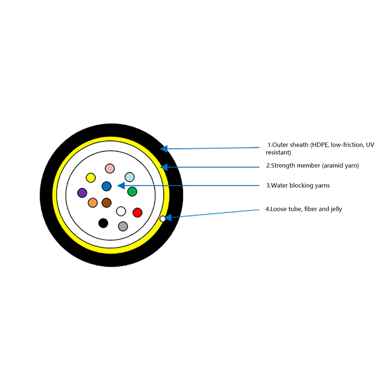
Before delving into procedures, it’s crucial to understand what sets Air Blown Micro Cables apart. Typically ranging from 2mm to 6mm in diameter, these cables are designed for minimal friction and maximum flexibility. Their construction often consists of:
This minimalist design influences every subsequent step in splicing and termination, demanding precision and specialized techniques.
The process begins long before the fusion splicer is powered on.
1. Cable Access and Extraction:
Unlike traditional cables pulled through large conduits, Air Blown Micro Cables reside within a microduct (typically 5mm to 14mm in diameter). To access the cable, a technician must first carefully cut into the microduct using a dedicated tube cutter. The goal is to create a clean, perpendicular opening without scoring the cable jacket beneath. The micro cable is then gently extracted, leaving sufficient service loop (recommended 3-5 meters on each side) for splicing and future re-work. This loop is often stored in a closure or slack box.
2. Stripping the Micro Cable:
This is a step requiring exceptional care. Standard cable strippers are often too large or aggressive for micro cable jackets. Instead, micro-cable stripping tools are used. These tools allow for precise, adjustable depth cutting to remove the outer jacket without damaging the aramid yarn strength members or the underlying buffer tube. The aramid yarn is then trimmed back neatly using high-quality scissors. The final step involves stripping the protective coating from the individual fibers using precision fiber strippers, a process identical to standard fiber work but performed on a smaller, more delicate scale.
Splicing involves permanently joining two optical fibers end-to-end. For Air Blown Micro Cables, the preferred method is fusion splicing.
1. Cleaving:
A perfect cleave is non-negotiable for a low-loss splice. The fiber must be scored and broken to create a mirror-flat, perpendicular endface. Electric cleavers are universally used in professional settings to ensure consistent, high-quality cleaves. Given the small size of the fibers, visual inspection with a fusion splicer’s built-in microscope or a separate fiber inspection probe is mandatory to check for defects before splicing.
2. Fusion Splicing:
The core process uses a fusion splicer, which aligns the two fiber ends with sub-micron accuracy. The splicer applies a small electric arc that melts the glass ends, fusing them together permanently. Modern splicers have profiles specifically for standard single-mode (SMF) or multimode (MMF) fibers, which are applicable to Air Blown Micro Cables.
Special Considerations for Air Blown Micro Cables:
3. Splice Loss Testing & Documentation:
Every splice is measured for optical loss by the fusion splicer using a Local Injection and Detection (LID) method or via an OTDR (Optical Time Domain Reflectometer) trace post-completion. Acceptable loss is typically < 0.05 dB for single-mode fibers. These results, along with splice locations and identifiers, are meticulously documented for the network’s records.
Termination involves fitting the fiber with a connector (e.g., LC, SC) to plug into equipment or a patch panel. For Air Blown Micro Cables, two primary methods are used.
1. Pre-terminated Solutions:
Increasingly popular, this involves ordering Air Blown Micro Cables with factory-installed connectors on one or both ends. These connectors are protected by robust breakout boots or pullable leaders that are designed to withstand the blowing force. After installation, the protective cap is removed, and the connector is ready for use. This method eliminates field termination work, guaranteeing optimal connector performance, but requires precise measurement of duct runs.
2. Field Termination:
When pre-termination isn’t feasible, field termination is performed. Due to the cable’s small diameter, a direct connector crimp is often not possible. The standard approach is:
This is arguably the most critical step specific to the ecosystem of Air Blown Micro Cables. The delicate splice points and the transition from the flexible micro cable to a more robust patch cord or distribution cable must be impeccably managed.
A micro duct/micro cable-specific closure is used. These closures are designed to:
Splicing and terminating Air Blown Micro Cables is a discipline that blends standard fiber optic precision with specialized techniques for unique micro-cable anatomy. The process is not inherently more difficult than working with traditional cables, but it does demand a focused understanding of the correct tools, closures, and strain-relief principles. By prioritizing careful preparation, flawless fusion splicing, and—most importantly—proper mechanical anchoring and protection within a suitable closure, network technicians can ensure that the inherent speed and flexibility of the Air Blown Micro Cable installation translates into a reliable, low-loss, and future-proof fiber optic link. The key lies in respecting the cable’s design: its installation is revolutionized by air, but its performance is secured through meticulous, hands-on craftsmanship at the point of connection.


 Layer Stranded Optical Fiber Ribbon Cable")

 Outdoor layer Stranded 8-shaped Self-Supporting Optical Cable")


Request for a call today
 Login
Custom Optical Cables Manufacturers
Login
Custom Optical Cables Manufacturers