


 English
 русский
 Español
 عربى
عربى 中文简体
中文简体

Optical Ground Wire (OPGW): Selection, Installation & Performance
Content
- 1 What Is Optical Ground Wire (OPGW)?
- 2 OPGW Construction and Fiber Types
- 3 Key Performance Specifications
- 4 OPGW versus Alternatives: ADSS, OPPC, and Traditional Ground Wire
- 5 Installation Best Practices and Considerations
- 6 Selection Guide: Matching OPGW to Your Overhead Line
- 7 Standards and Compliance
- 8 Maintenance and Long‑Term Reliability
- 9 The Bottom Line on Optical Ground Wire
When a high‑voltage transmission line takes a lightning strike, the ground wire isn’t just a passive shield—it can also carry terabytes of data. Optical ground wire (OPGW) makes this possible by embedding optical fibers inside the very strand that protects overhead conductors from lightning and short‑circuit faults. Utilities and transmission grid operators have adopted OPGW as the standard solution for adding fiber‑optic communication to new and existing power lines.
In this article, we break down exactly what OPGW is, how it is constructed, how to select the right specification, and what installation practices ensure decades of reliable service. Whether you’re engineering a 132 kV line or upgrading a 400 kV backbone, understanding the interplay between electrical grounding and fiber performance is critical.
What Is Optical Ground Wire (OPGW)?
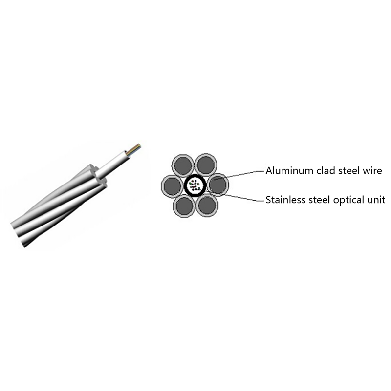
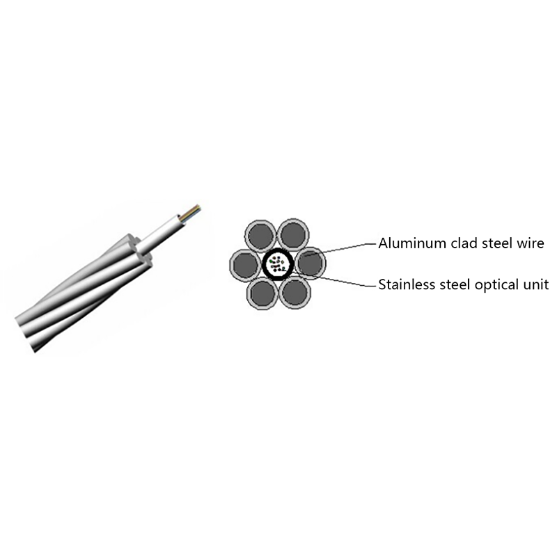
OPGW is a composite overhead ground wire that contains single‑mode or multi‑mode optical fibers within a metallic tube, surrounded by layers of aluminum‑clad steel and/or aluminum alloy wires. It serves two distinct roles simultaneously: protecting the phase conductors from lightning strikes and short‑circuit currents, and providing a high‑capacity communication path for teleprotection, SCADA, and broadband networks.
Unlike separate fiber‑optic cables lashed to existing ground wires, OPGW integrates the fiber inside the earth wire itself. This design eliminates the need for a separate fiber‑optic messenger and reduces wind and ice loading. An OPGW cable is factory‑manufactured to meet both IEC and IEEE standards, with fiber counts typically ranging from 12 to 144 fibers.
OPGW Construction and Fiber Types
OPGW construction balances electrical performance and mechanical strength. The core optical unit—usually a loose tube or a tight‑buffered design—sits at the center, protected by one or more layers of metallic strands. These strands not only carry fault current but also provide the rated tensile strength (RTS) and protect fibers from crushing and moisture ingress.
Metallic Armor and Strength Members
The outermost layer typically consists of aluminum‑clad steel (ACS) or aluminum alloy wires. ACS wires offer high conductivity for fault current dissipation while maintaining tensile strength. All‑aluminum alloy designs are available for corrosive coastal environments. The choice of wire diameter and material directly affects the OPGW’s short‑circuit current rating (often 10–50 kA for 0.5 s) and its overall diameter, which ranges from 9 mm to over 20 mm for high‑fiber‑count designs.
Optical Fiber Configuration
Inside the central tube, fibers are arranged in bundles, ribbons, or individual loose tubes. The tube is filled with a water‑blocking gel to prevent moisture migration. Fiber types conform to ITU‑T G.652 (standard single‑mode), G.655 (non‑zero dispersion‑shifted), or G.657 (bend‑insensitive) depending on the transmission distance and network requirements. Most OPGW installations use single‑mode fibers to cover spans up to 200 km without regeneration.
Key Performance Specifications
Selecting an OPGW requires matching the ground wire’s electrical and mechanical parameters to the transmission line’s design. The table below summarizes typical ranges seen in commercial OPGW products.
| Parameter | Typical Range |
|---|---|
| Fiber count | 12 – 144 |
| Overall diameter | 9.0 – 22.0 mm |
| Weight per unit length | 0.30 – 1.20 kg/m |
| Rated tensile strength (RTS) | 40 – 150 kN |
| Short‑circuit current (1 s, 200°C) | 10 – 50 kA |
| DC resistance at 20°C | 0.15 – 1.50 Ω/km |
| Maximum operating temperature | 80°C (permanent); 200°C (short‑term) |
| Fiber attenuation @ 1310/1550 nm | ≤0.35 / ≤0.22 dB/km |
The short‑circuit current capacity is critical. OPGW must survive the maximum expected fault current for the clearing time specified by the utility (commonly 0.5 seconds). Exceeding this rating can cause annealing of aluminum strands, fiber darkening, or catastrophic failure. Always verify the cable’s short‑circuit performance curve from the manufacturer’s type test reports.
OPGW versus Alternatives: ADSS, OPPC, and Traditional Ground Wire
While OPGW is the dominant choice for new transmission lines, engineers sometimes consider alternatives depending on project constraints.
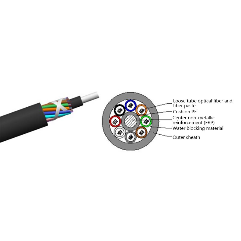
- All‑dielectric self‑supporting (ADSS) cable: Installed on the tower body rather than the shield wire peak, ADSS avoids electrical interference and can be added to live lines without an outage. However, it requires careful sag‑tension coordination and is more vulnerable to gunshot damage and aeolian vibration. For non‑ground‑wire applications, an ADSS (all-dielectric self-supporting) cable may be the right fit.
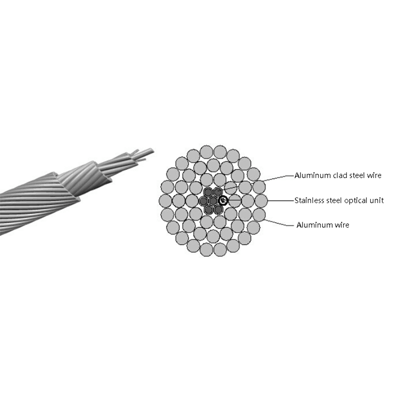
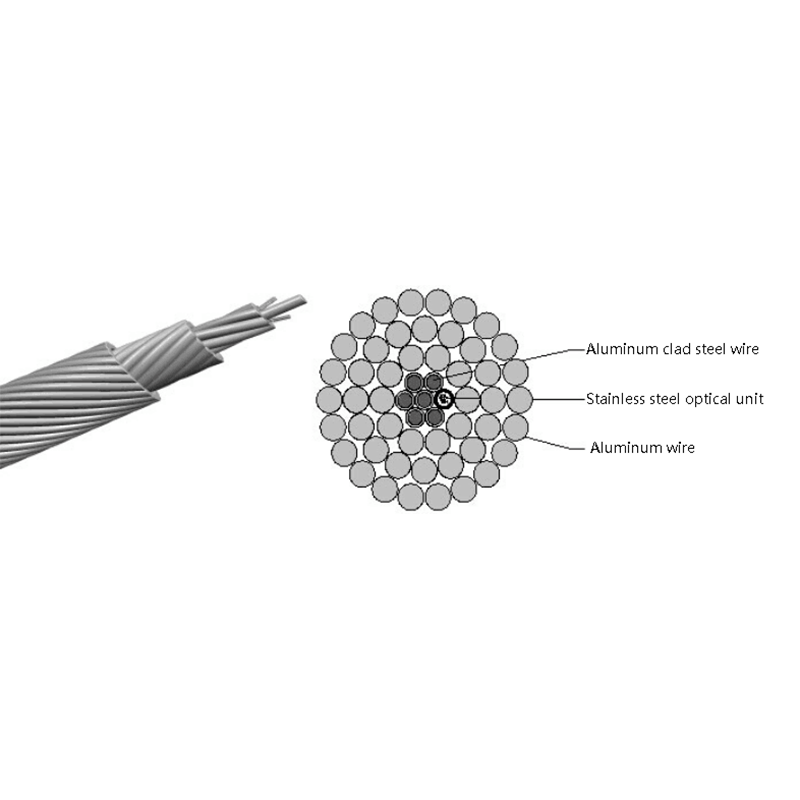
- Optical phase conductor (OPPC): This cable replaces a phase conductor and carries both power current and data. It demands special splicing and insulation design. Explore optical phase conductor (OPPC) cable for lines where a separate ground wire is not available.
- Traditional ground wire with lashed fiber: Older installations may retrofit a separate fiber cable onto an existing earth wire. This adds weight, wind load, and maintenance complexity—benefits OPGW avoids entirely.
For most greenfield transmission projects above 69 kV, OPGW remains the most reliable and cost‑effective option because it combines two functions into one strand and meets all relevant fault‑current requirements.
Installation Best Practices and Considerations
Installing OPGW requires specialized stringing equipment and careful handling to protect the fibers. Unlike a simple steel ground wire, OPGW must not be kinked, crushed, or subjected to excessive bending during pulling. Minimum bending radius guidelines (typically 20× the cable diameter under tension) must be strictly observed.
Key installation steps include:
- Pre‑installation testing: Verify attenuation, continuity, and OTDR traces on the reel before deployment.
- Stringing: Use tension‑limiters and anti‑twisting devices; pull with a suitable messenger line. The pulling tension must never exceed 20–25% of the RTS.
- Sagging: Apply the correct sag‑tension tables based on the ruling span and temperature. Over‑tensioning risks damaging fibers; under‑tensioning leads to excessive galloping and abrasion.
- Hardware: Use suspension clamps, dead‑ends, and vibration dampers designed specifically for OPGW to avoid crushing the fiber tube. Grounding clamps must provide a low‑resistance electrical path without damaging the optical core.
- Mid‑span splices: Fusion‑splice fibers inside weather‑proof closure boxes attached to the tower, maintaining proper slack for thermal expansion.
Never use standard ACSR grips on an OPGW; the optical unit will be crushed long before the hardware reaches its mechanical limit.
Post‑installation, an end‑to‑end OTDR test and splice loss measurement confirm compliance with design attenuation budgets. Properly installed OPGW can deliver a service life exceeding 30 years.
Selection Guide: Matching OPGW to Your Overhead Line
Engineers typically follow a four‑step process to select the optimal OPGW:
- Determine the required fiber count and type (G.652D is the most common for backbone networks).
- Calculate the maximum short‑circuit current (Ith) and clearing time at the point of installation, then request the manufacturer’s short‑circuit current curve to verify that the OPGW conductor cross‑section meets the thermal requirement.
- Derive the minimum breaking load from the design tension under worst‑case load conditions (ice, wind, everyday stress). The RTS of the OPGW must exceed this value with a safety factor of typically 2.5.
- Check the outer diameter and unit weight against the tower design and existing insulator/stringing hardware. If the line has ground‑wire peak already strung, a direct replacement OPGW with similar sag‑tension characteristics is preferred to avoid retensioning the entire span.
In retrofit scenarios, a common pitfall is selecting an OPGW with a higher unit weight than the original earth wire, causing excessive sag and reduced phase‑to‑ground clearances. Therefore, a detailed line survey and sag‑tension calculation is mandatory before finalizing the specification.
Standards and Compliance
OPGW products are tested and manufactured in accordance with internationally recognized standards. The most commonly referenced are:
- IEC 60794‑4: Optical fibre cables – Part 4: Sectional specification – Aerial optical cables along electrical power lines (OPGW).
- IEEE Std 1138: IEEE Standard for Testing and Performance of Optical Ground Wire (OPGW) for Use on Electric Utility Power Lines.
- ITU‑T G.652 / G.655: Characteristics of single‑mode optical fibre and cable.
Type tests include tensile performance, aeolian vibration, galloping, creep, temperature cycling, water penetration, and lightning arc resistance. Always request full type‑test certificates when sourcing OPGW for a new project.
Maintenance and Long‑Term Reliability
Once in service, OPGW requires minimal maintenance. The metallic sheath and water‑blocking gel provide inherent protection against humidity, and the entirely passive fiber path has no active electronics to fail. Annual inspections of suspension clamps, vibration dampers, and grounding connections are normally sufficient.
After a lightning strike, the OPGW might exhibit pitting or local strand melting. A post‑event OTDR trace can reveal any increase in attenuation from fiber darkening. If fiber attenuation exceeds the design margin, replacement of the affected span is necessary—a straightforward process because the hardware is standardized. Routine aerial inspections using drones equipped with thermal cameras help identify hotspots that indicate deteriorating electrical connections.
The biggest threat to OPGW longevity is not corrosion or aging but poor initial installation, especially insufficient slack at splices or inappropriate hardware that crushes the optical core. When those pitfalls are avoided, OPGW delivers a maintenance‑free communication backbone for the lifetime of the transmission line.
The Bottom Line on Optical Ground Wire
OPGW is no longer a niche product; it is the default choice for combining high‑speed fiber communications with robust overhead ground‑wire protection. Its dual‑function design reduces tower loading, eliminates separate cable runs, and withstands the harshest electrical and environmental stresses. For utility engineers, the key lies in matching the mechanical and electrical properties to the specific line conditions—fault current, span length, and fiber count—and following installation protocols that preserve the optical integrity from the reel to the splice enclosure.
When deadlines are tight and reliability is non‑negotiable, choosing a proven OPGW cable backed by full type‑test documentation and field experience keeps both the grid and the data flowing.
Related Products
-
Optical Phase Conductor OPPC Cable
-
GYXTW Central Tube Armored Outdoor Optical Cable
-
Fiber Optic Patch Cables
-
OPGW Optical Fiber Composite Overhead Ground Wire
-
GYDTA(S) Layer Stranded Optical Fiber Ribbon Cable
-
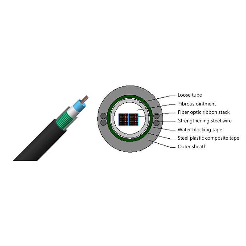
GYDXTW Center Tube Outdoor Optical Fiber Ribbon Cable
-
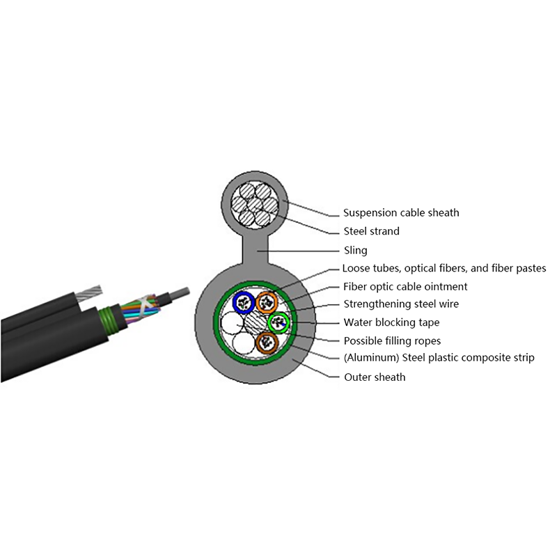
GYTC8A (S) Outdoor layer Stranded 8-shaped Self-Supporting Optical Cable
-
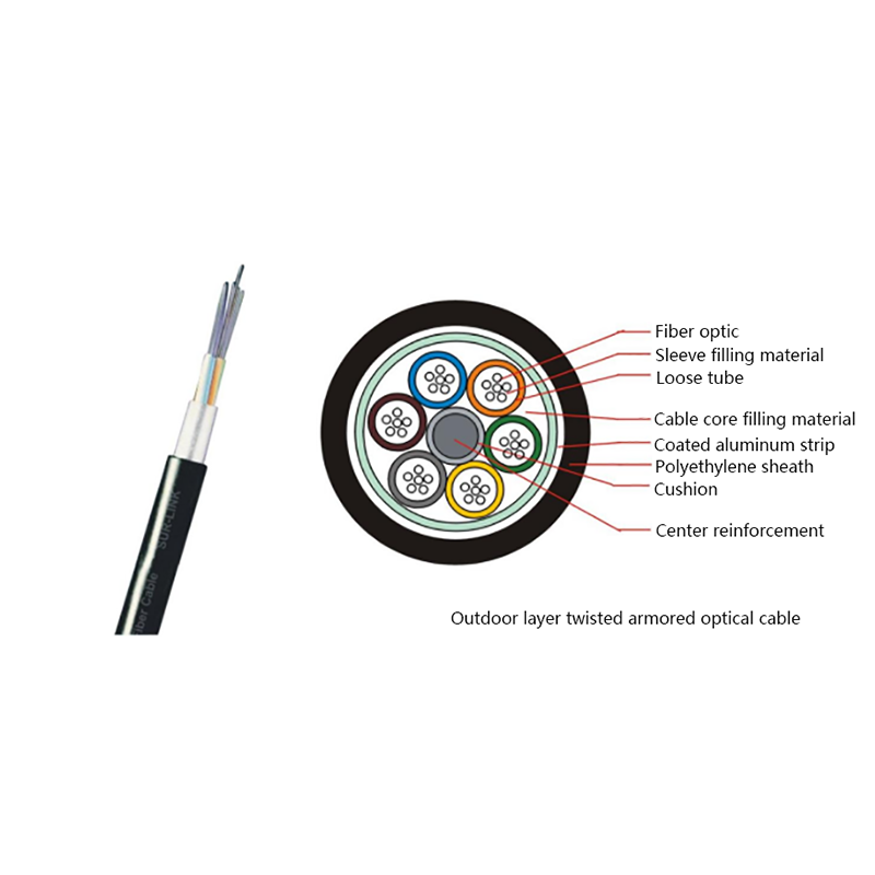
GYTA Layer Stranded Aluminum-Polyethylene Bonded Sheathed Outdoor Optical Cable
-
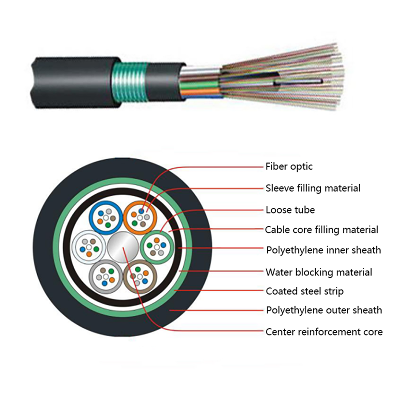
GYTY53 Layer-Stranded PE Inner Sheathed Steel Tape Armored Outer Sheath Optical Cable
-
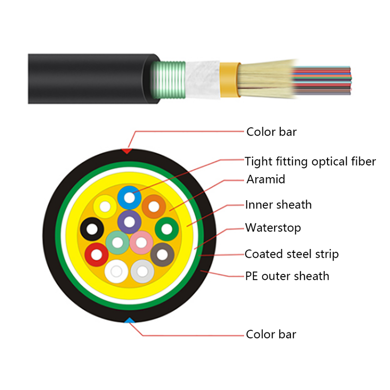
GJFJH53 Indoor Bundled Steel Tape Armored Optical Cable
-

GJPFJV GJFJHV Indoor Branch Optical Cable
-
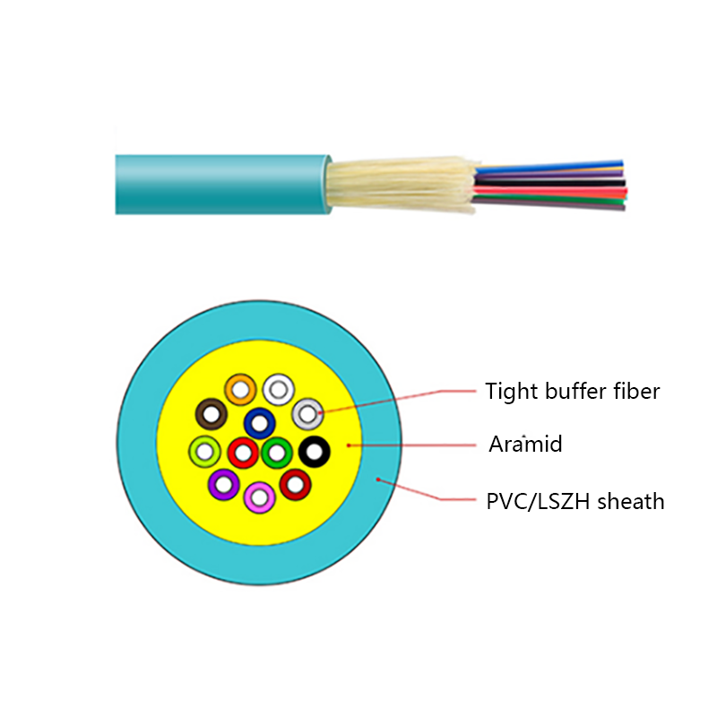
GJFJV Indoor Single Bundle Fiber Optical Cable
-
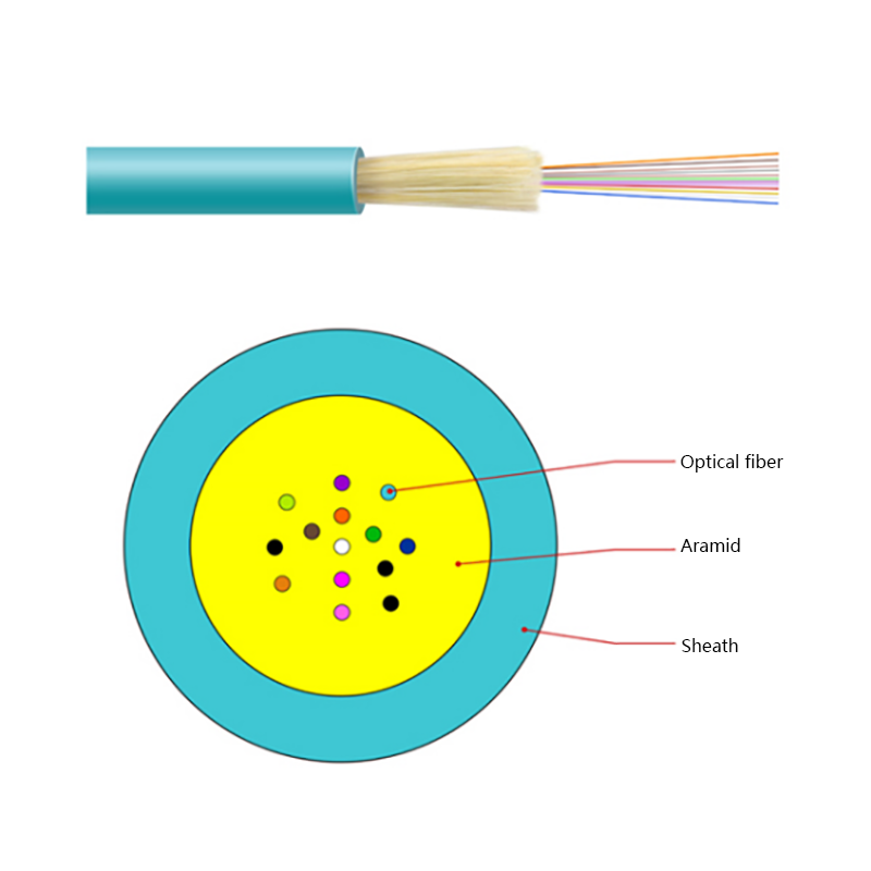
GJFV Indoor Mini Bundle Fiber Optic Cable
-
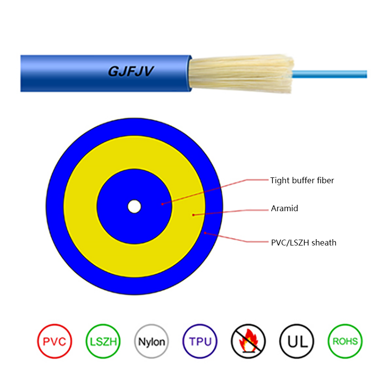
GJFJV Indoor Single Core Jumper Wire Optical Cable
-
Indoor Tight-Buffered Fibre Optic Cable
-
ADSS—All-Dielectric Self-Supporting Optical Cable
-
Anti-Squirrel ADSS Optical Cable
-
Non-metallic optical cable
Looking For Bussiness Opportunity?
Request for a call today

- Tel: +86-139-6297-6666
- Whatsapp: +86-13962991888
- E-mail: [email protected] / [email protected]
- Add: No.18, Xinjing Road, Nantong Economic and Technological Development Zone, Jiangsu Province, China
Products
Message
Coprright 2023 Jiangsu Hawell Optoelectronic Technology Co., Ltd. All Rights Reserved
 Login
Custom Optical Cables Manufacturers
Login
Custom Optical Cables Manufacturers
Login
Custom Optical Cables Manufacturers