

 English
 русский
 Español
 عربى
عربى 中文简体
中文简体
What Does Fiber Optic Cable Do?
Content
Fiber optic cables transmit information as pulses of light through strands of glass or plastic. They serve as the backbone of modern telecommunications, enabling high-speed data transfer over long distances with minimal signal loss.
Core Functionality
Fiber optics convert electrical signals into light using a transmitter. Light travels through the cable via total internal reflection, bouncing between the core and cladding. At the destination, a receiver converts light back into electrical signals.
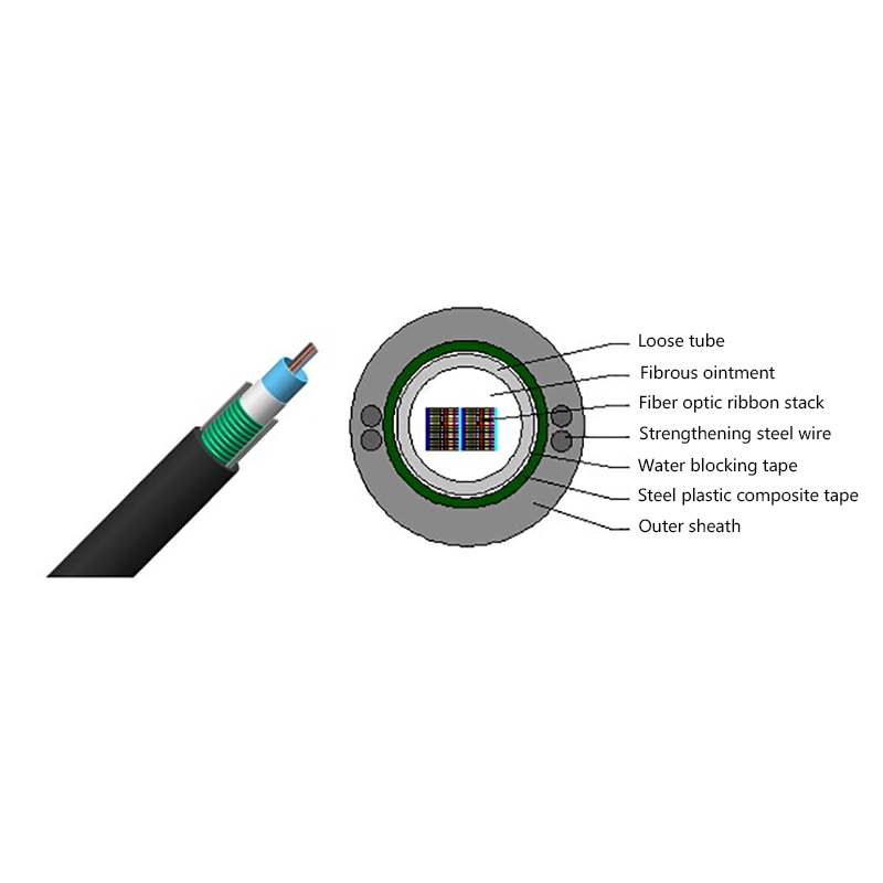
Key Components
• Core: Thin glass/plastic center carrying light
• Cladding: Outer layer reflecting light inward
• Buffer coating: Protective plastic jacket
• Strength members: Reinforcing fibers (e.g., Kevlar)
• Outer jacket: Weather-resistant exterior
Technical Specifications
Single-mode fibers (9µm core) carry infrared laser light (1310-1550nm) for distances exceeding 100km. Multimode fibers (50-62.5µm core) use LED light sources for shorter runs (≤2km).
Performance Comparison
| Feature | Fiber Optic | Coaxial Cable | Twisted Pair |
| Max Bandwidth | >100 Tbps | 10 Gbps | 10 Gbps |
| Max Distance (no repeaters) | 80-100km | 500m | 100m |
| Latency | 5μs/km | 10μs/km | 12μs/km |
| EM Interference Immunity | Complete | Moderate | Low |
| Typical Applications | Internet backbone, submarine cables | Cable TV, CCTV | Ethernet, telephony |
Signal Transmission Mechanics
Light pulses maintain signal integrity through total internal reflection. The critical angle calculation follows Snell's Law: θc = sin-1(n2/n1), where n1 and n2 are refractive indices of core and cladding.
Deployment Scenarios
• Undersea Cables: 400+ systems spanning 1.3M km globally
• FTTH (Fiber-to-the-Home): Direct consumer connections
• Data Centers: Spine-leaf architecture with 400Gbps links
• Industrial: EMI-resistant factory automation
Limitations and Considerations
Installation costs exceed copper by 10-30%. Specialized equipment required for splicing (0.1dB loss per splice). Minimum bend radius (typically 10-20× cable diameter) prevents light leakage.
Evolution Timeline
1977: First commercial installation (Chicago)
1988: TAT-8 transatlantic cable (40,000 calls simultaneously)
2016: 4,000km record (1Tbps single-channel)
2023: Subsea systems achieving 24Tbps per fiber pair
Future Developments
Space-division multiplexing using multi-core fibers (7 cores demonstrated). Hollow-core fibers reducing latency to 3μs/km. Integration with quantum cryptography networks.
Technical Deep Dive
Fiber optic systems leverage wavelength-division multiplexing (WDM) to increase capacity. Dense WDM (DWDM) supports up to 160 wavelengths per fiber, each carrying 100Gbps. Signal regeneration occurs through erbium-doped fiber amplifiers (EDFAs) spaced at 80-100km intervals, maintaining optical amplification without electrical conversion. Nonlinear effects like four-wave mixing become significant at power levels exceeding +17dBm, requiring dispersion-shifted fiber designs. Polarization mode dispersion (PMD) compensation is critical for links beyond 40km operating at 100Gbps+.
Material Science
Ultra-pure fused silica (SiO2) forms the core material, with germanium doping increasing refractive index. Cladding uses fluorine-doped silica with 0.36% lower refractive index. Manufacturing involves modified chemical vapor deposition (MCVD), where gases deposit silicon layers inside preform tubes at 1900°C. Fiber drawing occurs at 2000°C, pulling 10km/min with diameter controlled to ±0.1µm.
Related Products
-

Optical Phase Conductor OPPC Cable
-

GYXTW Central Tube Armored Outdoor Optical Cable
-

Fiber Optic Patch Cables
-

OPGW Optical Fiber Composite Overhead Ground Wire
-
 Layer Stranded Optical Fiber Ribbon Cable")
GYDTA(S) Layer Stranded Optical Fiber Ribbon Cable
-
GYDXTW Center Tube Outdoor Optical Fiber Ribbon Cable
-
 Outdoor layer Stranded 8-shaped Self-Supporting Optical Cable")
GYTC8A (S) Outdoor layer Stranded 8-shaped Self-Supporting Optical Cable
-

GYTA Layer Stranded Aluminum-Polyethylene Bonded Sheathed Outdoor Optical Cable
-

GYTY53 Layer-Stranded PE Inner Sheathed Steel Tape Armored Outer Sheath Optical Cable
-

GJFJH53 Indoor Bundled Steel Tape Armored Optical Cable
-

GJPFJV GJFJHV Indoor Branch Optical Cable
-

GJFJV Indoor Single Bundle Fiber Optical Cable
-

GJFV Indoor Mini Bundle Fiber Optic Cable
-

GJFJV Indoor Single Core Jumper Wire Optical Cable
-

Indoor Tight-Buffered Fibre Optic Cable
-

ADSS—All-Dielectric Self-Supporting Optical Cable
-

Anti-Squirrel ADSS Optical Cable
-

Non-metallic optical cable
Looking For Bussiness Opportunity?
Request for a call today
- Tel: +86-139-6297-6666
- Whatsapp: +86-13962991888
- E-mail: [email protected] / [email protected]
- Add: No.18, Xinjing Road, Nantong Economic and Technological Development Zone, Jiangsu Province, China
Products
Message
Coprright 2023 Jiangsu Hawell Optoelectronic Technology Co., Ltd. All Rights Reserved
 Login
Custom Optical Cables Manufacturers
Login
Custom Optical Cables Manufacturers
Login
Custom Optical Cables Manufacturers